LETU Rube Goldberg Machine

Standard

One of the standard rites of passage during a electrical engineering student’s time at LeTourneau is the Rube Goldberg demonstration which is a part of Electronic Design Lab, also known as ELAB III. This course contains a variety of requirements which are separated into modules, labs and lab reports, mini-labs, and quizzes and tests. 65% of your course grade depends on the lab reports and modules. These modules are projects that the student must individually design, build, and demonstrate such as a DC power supply, a function generator, and a 10 watt power amplifier and the labs cover material from RC and RL transients to transmission line theory. The other 35% of the class is distributed between quizzes, the final, and a few other small assignments.

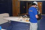
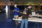
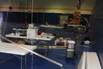
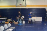
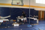
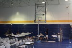
One of the most enjoyable and yet exhausting modules/labs was the Rube Goldberg demonstration which is held each April. The goal is to design and construct a machine which accomplishes a trivial task through a long, strung-together series of transitions. As our group of three began to brainstorm ideas for our machine, we settled on a musical journey, noisily progressing towards the finale, popping a large balloon.

The steps were as follows:

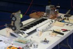
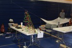
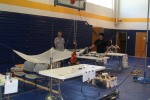
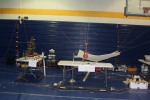
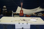
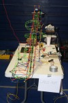
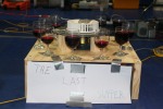
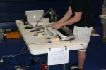
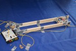
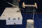
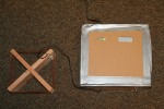
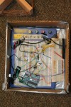
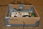
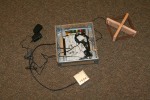
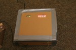
First, the ukuledulum, a ukulele suspended from the gym ceiling, swings over a distance sensor which produces a clicking sound like a metronome when the ukulele reaches the bottom of its swing. After 5 clicks, the Arduino connected to the distance sensor sends an infrared signal to trigger the car which is waiting on a set of rails. The car travels down the rails, crashing at the end into a bump switch which triggers a set of relays and turns on the music box keyboard and the wine glass carousel. These begin playing and a string winds around the spindle of the music box keyboard and ultimately pulls out a magnetic switch which releases a ball, sending it sliding down the metal ramp and crashing into the oversized Newton’s cradle at the bottom of the slide. The transition from the Newton’s cradle causes the last ball in the cradle to press a limit switch and trigger a rubber band car via infrared. This car again travels down a set of rails and crashes into another switch, triggering the razor-blade cutting machine which slices the string which keeps the ladle-put set to fire. After the razor-blade cuts through the string, the ladle-put releases, catapulting a ball into a large plastic tablecloth funnel. The ball then travels down into a cup at the bottom of the funnel, striking a switch which activates the mini-knex boom coaster equipped with needles. The coaster travels down and around its rails and pops the balloon, ending the musical journey with a large bang. Below are pictures of the different parts and finally a video of the entire machine. Hope you enjoy seeing the results of our project. Feel free to share with others!

Arduino Temperature Monitor

Standard

The semester is finally coming to a close which means I might finally get a chance to breathe deeply again and write about all the projects I’ve been working on this semester. This past week I’ve been finishing up a few smaller projects for my Electronic Design Lab course. I’ve really enjoyed getting to build stuff this semester and apply some theory in real life. (Who knew!) One of these projects I have been working on is a module which senses the ambient temperature using an Arduino and some output LEDs (eventually an LCD when I get around to buying one) to display this information. I’m hoping to be able to continue this design and make a more permanent version for some other ideas I have.

I used some CAT5 ethernet cable as an extension for the temperature sensor so as to allow for the actual sensor to be placed a distance from the Arduino unit. For the display unit, I used a 10 LED bar graph module and hooked the LEDs up to the digital output pins using 330 ohm resistors. I also connected a piezo buzzer to one of the PWM pins so as to allow for an alarm.

The physical layout for the device is below:

The schematic:

The code for the Arduino is pretty simple, taking the input temperature from the LM35 sensor in the form of an analog voltage value and converting it to a digital value and finally to a temperature using the equation for the LM35: 

Then, this value is converted to degrees fahrenheit and the result printed to the serial monitor. Following this, the value is mapped to the number of LEDs using the baselineTempF and maxTempF values declared as global variables at the beginning of the sketch. Using this value, a for loop is entered in which the appropriate LEDs are turned on and all others turned off. A piezo buzzer is also connected on pin 3 as an alarm if the temperature rises above a user-configured value, or if the temperature is above or below the set range of detection.

The complete code is attached here.

The prototyped version of the device looks like this:

The Arduino with Bar Graph LED and LM35 Sensor
Arduino and LED Bar Graph Close Up
LM35 Sensor Cable Close Up

Future plans for this include creating a more permanent module with the Arduino integrated onto a PCB or protoboard, extending the sensing functionality and precision of the device, and adding additional methods to output the data. Please leave your questions or comments!

Electronics 1 Project: Wireless Remote Help Station

Standard

Last semester for my Analog Electronics I class we were required to complete a project using a form of radio communication. The project was very open ended, but the goal was to create a product which could be used to be used in a service oriented application. While this requirement was vague, we narrowed the project scope and decided to create an wireless, itemized help request system for someone in a limited mobility situation to contact help. Throughout the course of the project we learned a great deal about radio transmission, amplifier design, and antenna design. Here are some pictures of the final product as well as some shots from along the way.

The transmitter consisted of a square wave oscillator circuit using an LM741 Op-Amp, a Colpitts Oscillator, a modulator, and an amplifier. By switching in different resistance values in parallel with the resistance value which created the base frequency, the frequency of the square wave generated by the LM741 Op-Amp could be changed. This signal was then modulated using a 2N3904 BJT with a carrier sine wave with a frequency of about 550 kHz. After this stage the signal was then amplified and sent to the antenna.

On the receiver side, the signal passed through the antenna and then was filtered to remove any unwanted frequencies. After the filter, the signal was sent through a cascode amplifier and cascaded through another common emitter amplifier. After this initial amplification, the envelope detector was next. The envelope detector essentially uses a diode and an RC network to filter only the positive side of the signal and to filter out the high frequency carrier, passing only the square wave data signal. It is important to note that the signal must be strong enough to overcome the internal 0.7 V bias of the diode in order for the detector to be effective. Finally the signal was amplified once again and the output transmitted to an Arduino Duemilanove for decoding.

Now that you’ve had a chance to see what the actual device looks like and the schematics it’s time for some theory! The radio transmission method we used is called Amplitude Shift Keying (ASK). Essentially, the amplitude of some data signal (a square wave in our case) is modulated or combined with a high frequency carrier wave which allows the signal to travel through the air. Then, the receiver takes the signal it receives at its tuned frequency and demodulates it to regain the data signal (square wave). Finally, this signal is processed and an action performed. In our project, we used an Arduino Duemilanove (arduino.cc), a popular open source microcontroller, to process the frequency of the square wave and light up certain display LEDs on the panel to indicate which switch was activated at the input. This provided flexibility in our design, allowing us to customize the frequencies for each setting on the fly and also do some simple signal processing. Although the quality of our homemade antennas crippled the range of our system, this project provided us with a practical application of antenna theory, radio transmission, and most importantly, transistor theory.

Thanks for reading and please feel free to leave questions or comments!